Публикуется в электронном виде на правах учебного курсового проекта.
The UHF-wavelines
The UHF-line design is defined by some rules and this must be known.
An any antennas may be designed only as this surfaces: a dipoles (a halfwave vibrators), a quarterwave vibrators, a circuits, a UHF-wavelines with a form that to a boxes.
The dipoles
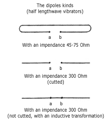
All antennas has construction by those elements. We can say that any piece of a metal circuit can work as a passive fider that is a re-transmitter of a radiowave that has a lengthwave that calculate by a classic physical formula for this equipment.
The points a and b is shown as a connection places for a reciever or a transmitter equipment cable.
UHF-wavelines

The UHF-waveline is an UHF-antenna. The internal side size of one from four sides is equal by a halfwave for work friquency. Points a and b is shown connection places for reciever or transmitter equipment cable. A transmitting or a listening is provides by an open hole as shown in right side on the figure. A groover is a thin work friquency detail. The distance from point a to UHF-waveline downside is equals to quarter of a lengthwave. The UHF-waveline length is equals to any number of a lenghthwave.
A circuits
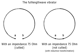
The length of a circuit (a circle) is equal to a lengthwave. The points a and b is shown as a connection places for a reciever or a transmitter equipment cable.
The quarterwave vibrator
Any conductive (a metal) bar that is stands to metal plate in a vertical position can work as a quarterwave vibrator and length of this is an equal to quarter of a lengthwave with the coefficient (about 0.98) because of a lengthwave in an air is a smaller than on a metal surface.
The antenna design
What is type of an antenna?
1 - a circuit (to measure an internal diameter)
2 - a box (to measure bigger internal side and get a halfwave length)
3 - a dipole (to measure bigger an internal side and get a halfwave length)
4 - a dipole (to measure a length and get a halfwave length)
5 - a cable pack (to measure an external and an internal diameters and get after calculate two friquencies that this "antenna" will works from a first to a second friquencies values)
6 - four quarterwave vibrators that placed onto the metallic plate (to measure each and get four quarterwave values)
7 - the metallic plate with "the cutted windows". "The quadrate window" calculate as a halfwave dipole and the circles as the circuits and "an ellipse" as a dipole.
8 - a box (to measure a bigger internal side and get a halfwave length)
9 - a pipe (to measure an internal diameter)
10 - a thin pipe (to measure an internal diameter)
11 - a circuit (to measure an internal diameter)
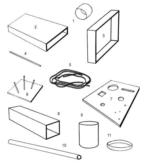
The handmade design of an UHF-antenna
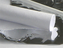
To calculate diameter value for the work friquency then made a paper pipe with an external diameter that must be an equal to this value.
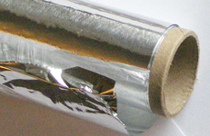
For covering we can use a simple aluminium foil. The foil must lays by a brighter side to a paper surface.
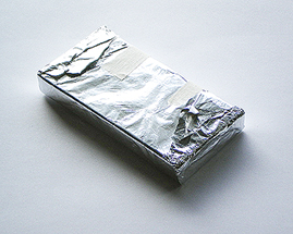
The rubber "an aspirine" box that covered by an aluminium foil can work as an UHF-waveline box.
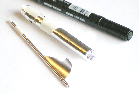
Many plastic things can be covered by an aluminium foil. The plastic things that made from black plastic can not work in an UHF because of this contain part of a carbon that will decrease an UHF-energy.
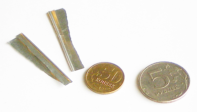
The microwavelines: an internal diameter is an equal less than 0.5 mm.
Vacuum covering by a metals.
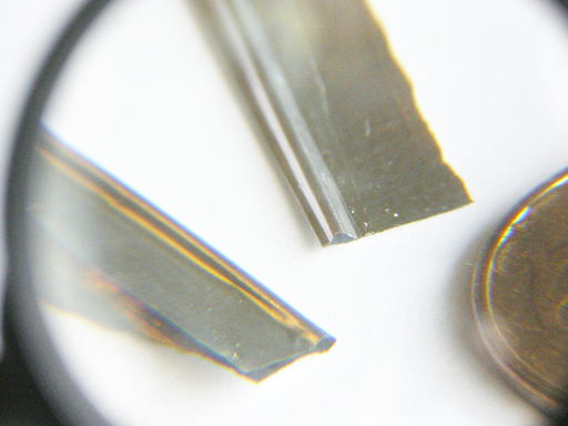
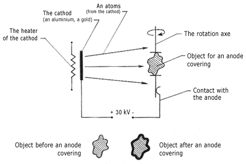
If you need have a very smaller metal pipes then we can get a simple hairs then place this in the vacuum post equipment and power on. Such ordinal equipment as a vacuum post is placed in many universities and an institutes. A vacuum post can cover thin metallic (f. e.: gold, aluminium) lay to hair surface. Of course, one smaller "a metallized" hair can not good effect but many (f. e. 10,000,000) hairs from some horse tails can bring an exellent effect for a teraherz UHF-range work.
The fighting against an UHFRLAN
For temporary destruction one or more UHFRLAN-segments f. e. if this is used by a hackers for an intruding to your LAN or WAN you need to destroy their UHF-matrix that is an units in an each UHFRLAN. As we shown in other page - the strong electromagnetic fields can damage the UHF-matrix. We can make an extremely power EMP by a battery from some electrolithic capacities in a parallel connection design. For example we can to use the capacities with 2,000...10,000 microfarades for 50...100 volts. So we need charge this battery by the power electric DC-source and made "big boom" with any UHF-waveline by connection "+" and "-" electrodes of battery by an UHF-waveline surface. Such equipment made power EMP in an UHF-range then part of an UHF-matrix will be damaged and an UHFRLAN will shut down. Test traffic in your root before and after this by ip-analyser software. If this traffic differs then your LAN or WAN has an intruders.
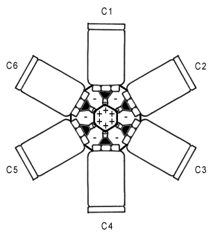
So strange a capacities placement is defined by an important reason: the all electrodes must be shorty as a possible!
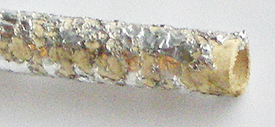
An aluminium vapooration by "the big boom" with the handmade EMP. Two foil lays is vapoorate in high temperature for some milliseconds. Photo made with x3 increase.
[Index]
© 2009 г. Сайт оптимизирован для удобного чтения на мобильных телефонах. Сайт подготовлен при поддержке специалистов компании [Гротек]. Данный сайт не содержит какой-либо (любой) противоправной, а равно - противозаконной информации, либо информации нарушающей чьи-либо гражданские права, а также не сообщает какой-либо (любой) иной (другой) информации могущей привести к противоправным деяниям, если таковые наступают в результате неправильной трактовки этой информации, либо неправомерного ее применения.
